 1999, First-Grade Homework")

STMicro’s documentation about the subject is some of the most terse documentation I’ve ever seen in the business! This cheat sheet is a work-in-progress.
DM-What?
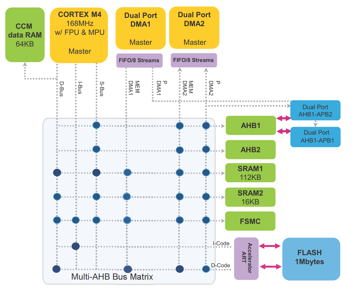
The STM32 microcontroller family has 2 DMA controllers, and 16 DMA “streams”. Streams are pathways where memory can flow, and each processor has 8 to work with.
The DMA1 controller has two ports: a memory port that can access system memory, and a peripheral port which can access the peripheral bus. It is faster to use this controller when talking to peripherals, as it has a direct connection to the peripherals which bypasses the bus matrix. Thus, it has only one connection to the bus matrix.
The DMA2 controller has three ports: two memory ports that can access system memory, and a peripheral port which can access the peripheral bus. This means DMA2 is also capable of memory-to-memory transfers (unlike DMA1), as it has two connections to the bus matrix.
The DMA controller can operate in the following ways:
- Peripheral-to-Memory Mode (DMA1, DMA2)
- Memory-to-Peripheral Mode (DMA1, DMA2)
- Memory to Memory Mode (DMA2 only)
Each controller has 8 “streams”, which independently support
- Hardware or software triggering.
- Double or circular buffering.
- Memory address incrementation on source and destination addresses.
- 4 x 32 bit FIFO which can be enabled or disabled.
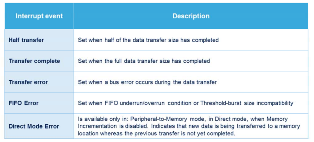
- Interrupt flags for half-transfer, transfer-complete, error…
Each stream’s priority can be set in software, but if two streams have equal software priority, the one with the higher hardware priority gets favored. In example, Stream 0 has higher priority than Stream 1.
Channels
The DMA controllers have access to a special bus (“AHB peripheral port”) which gives them rapid-access to selected peripherals. This is useful as it allows the standard bus matrix to be bypassed and latency to be significantly reduced.
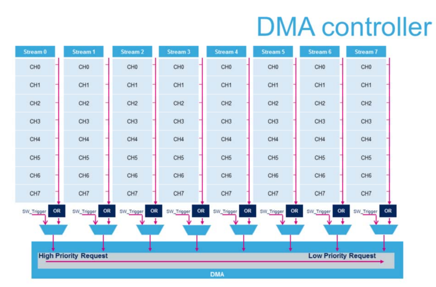
Each stream has 8 “channels”, which can be thought of as a multiplexer for the peripheral bus.
The channel selects a DMA trigger (“request”), which can be used to start the DMA transfer process based on a peripheral’s state and configuration. In example, a request may be initiated upon arrival of new data to a serial port peripheral.
The channels are OR’d with a software trigger that can manually invoke the DMA transfer process.
Addressing
The stream can access data as either a char, half-word, or word (int_8, int_16, or int_32). The source data size and destination data size are independently configurable.
Each stream has a source and a destination address pointer.
- In M2P mode, the source address could be an SRAM address, flash address, or any other address the DMA port may be connected to in the MCU’s bus matrix. The destination address must be a peripheral address on the AHB bus, though, the documentation is not clear on whether this address must be the specific peripheral of the selected channel, or any valid address in the AHB bus. Sean suspects that only the request triggers are channel dependent, and that any valid address on the bus may be chosen as the destination address.
- In P2M mode, the inverse of the above is true.
- In M2M mode, both source and destination addresses can be any address on the bus matrix which the DMA engine has access to. This can include peripheral addresses, which are handled by the memory manager of the bus matrix.
Both the source and destination pointer have an increment function which can be enabled or disabled. Upon every successful write, the address pointer will increment one data unit. Data units remember, are independently configurable for source and destination, so it is possible to read 16 bit units, yet increment the destination 32 bits at a time.
The maximum transfer size of the source buffer is programmable.
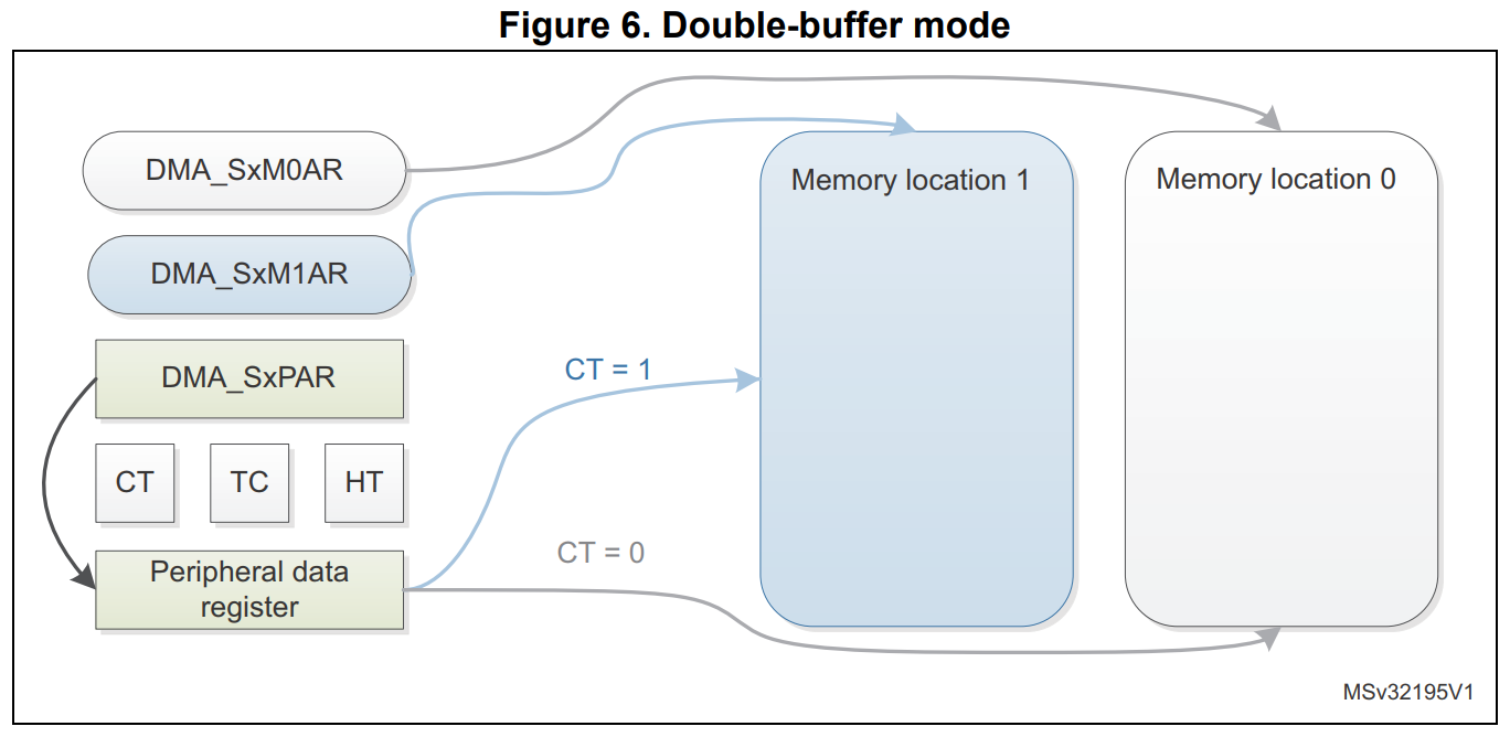
Circular mode is also supported, where, the address pointer is automatically reloaded after the source buffer has been emptied, and the DMA transfer process begins again. This can be useful for continuous data streaming.
Circular mode also has a double buffer mode, where, instead of reloading the initial pointer address, a second pointer address is reloaded, so that the buffer can be written to by a secondary program without any conflict.
Transfer Sizes
Transfers can happen either in a single burst, or incremental bursts of 4, 8 or 16 beats. This is a property of the DMA controller, not the individual streams.
The size of the burst is configured by software independently for the two AHB ports in the DMA_SxCR register. The burst size indicates the number of beats in the burst, not the number of bytes transferred.
I don’t fully understand this yet.
Peripheral to Memory
So if you want to move data from a peripheral to the DMA controller, to memory, and use the peripheral’s DMA request trigger as the event which starts the transfer,
- Choose a Stream (1 of 8)
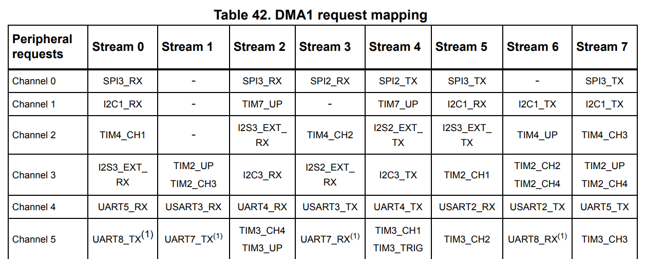
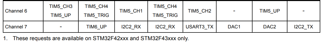
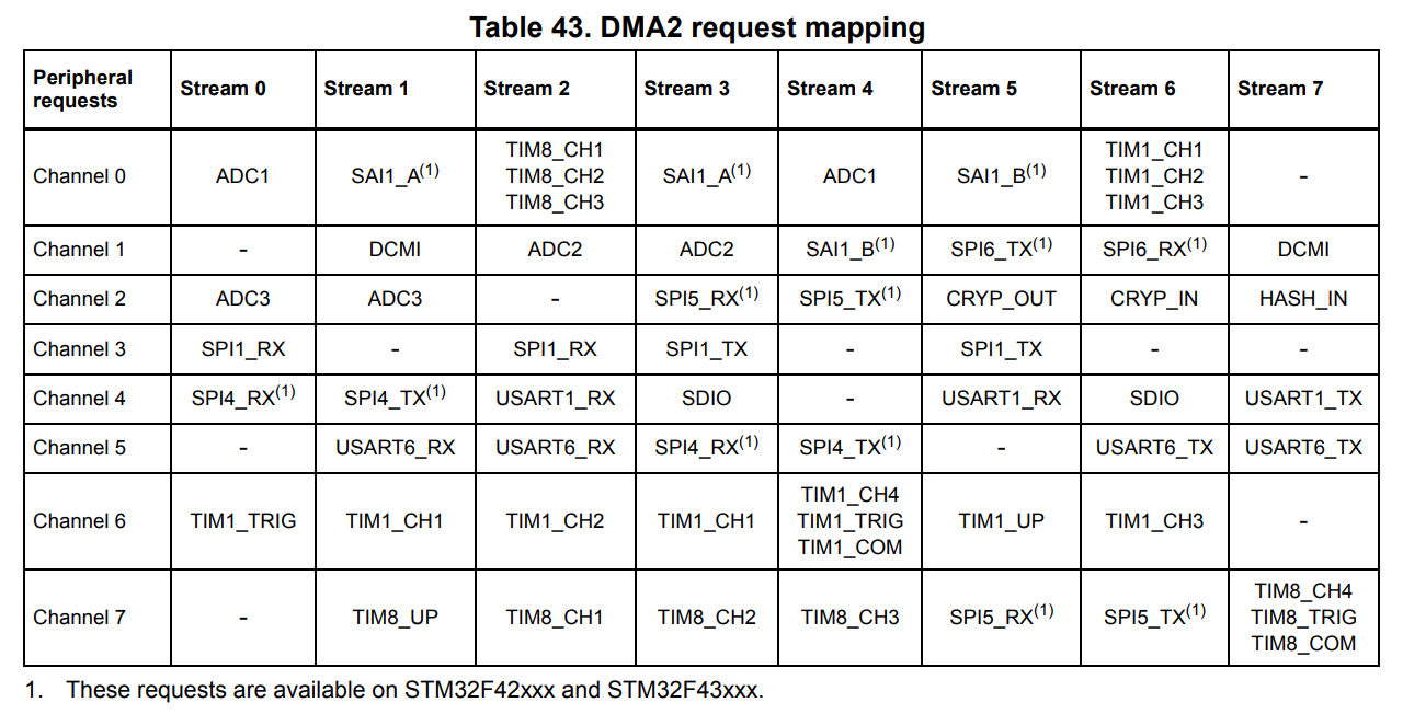
- Use the “DMA Request Mapping” table (specific to the MCU) to find out what is a valid channel for that stream and chosen peripheral.
This is an example table for the STM32F4 series MCU:
Alternatively, you can software trigger the DMA transfer by writing to a specific register.
After triggering the transfer, the DMA controller will read from the source address and either,
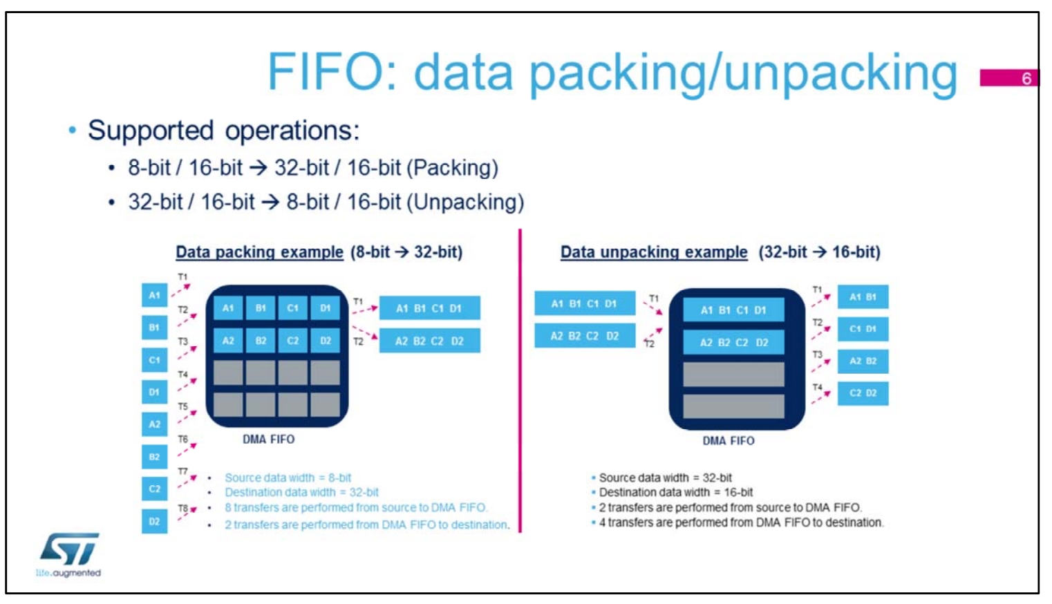
- Put that data into a 4 word FIFO
- Write that data directly to the destination address
Depending on your configuration.
Each DMA controller has a FIFO, which can be used as a buffer to store data. The FIFO will not empty unless either, 1/4 Full, 1/2 Full, 3/4 Full or 100% Full depending on your configuration. The FIFO can be used to reduce memory access reads or writes, which is helpful when data does not need to be used in exactly real time.
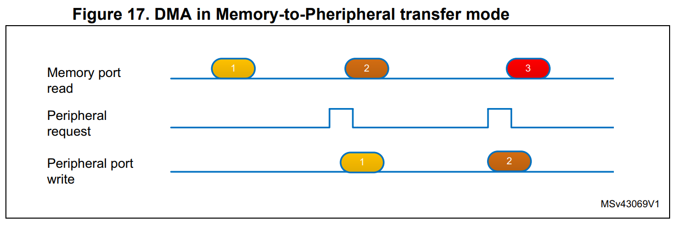
Memory to Peripheral
So if you want to move data from memory to the DMA controller, and use the peripheral’s DMA request trigger as the event which starts the transfer. It’s pretty much the same deal as before.
- Choose a Stream (1 of 8)
- Use the “DMA Request Mapping” table (specific to the MCU) to find out what is a valid channel for that stream and chosen peripheral.
- Depending on whether or not you enabled the FIFO, the data is either shuttled directly into the peripheral, or, is buffered for a bit until the peripheral is ready for it. This is possible because the DMA controller will actually preemptively fill the FIFO from memory for you.
Memory to Memory
Memory to Memory is a bit of a misnomer, as peripherals are also a part of memory you can also use this mode to update peripherals. The key difference is, in M2M mode, you are transferring data through the bus matrix and not the specialty DMA <–> peripheral pathway used in other modes.
The key reason to use this mode to access peripherals, is if you want to transfer to a peripheral without the request being initiated by the peripheral. Say for example, you wanted to update the state of a timer’s compare value for PWM generation, then you should use the memory-to-memory mode of DMA2.
In M2M mode, DMA transfers are started by software. The Stream begins transferring data…
- From source to destination immediately when its enable bit is set in DMA_SxCR
- Or in the case where FIFO is enabled, immediately filling the FIFO to the threshold level when the enable bit is set. When the threshold is reached, the FIFO is drained into its destination.
In both cases, the transfer stops either when…
- The enable bit is cleared in DMA_SxCR by software.
- The maximum size of the transfer is completed (DMA_SxNDTR is zero).
The stream only has access to the source or destination ports if it has higher priority than all the others, and the ports are not busy.
Interrupts
The DMA controller’s streams are capable of interrupt generation, which may be used to for example, load more data into the source buffer when the transfer is half-completed. This can be useful for say, reading data from an SD card or other storage, where the available memory of the MCU is less than that of the mass storage.
Arbitration
DMA transfers are not instantaneous, as the streams all share the same bus the speed of the transfer is a function of how much time the arbitrator allocates to the stream. The allocation is done in a round-robin fashion with bounded maximum latency, so a higher-priority DMA request can’t jam up the bus entirely for everyone else.
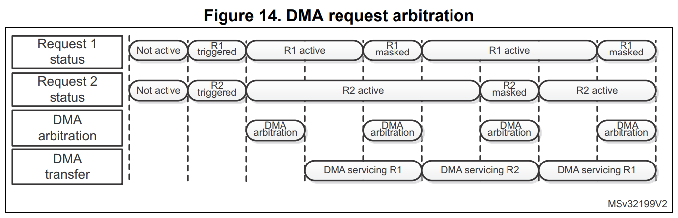
The high-speed/high-bandwidth peripherals should have the highest Stream priorities to ensure a high transfer rate. Since the two DMA controllers can work in parallel, high-speed peripherals’ requests should be balanced between the two.
In case of equal bandwidth requirements, it is recommended to assign a higher priority to the peripherals working in slave mode (which have no control on the data transfer speed) compared with the ones working in master mode (which may control the data flow).
HAL Functions
The DMA HAL driver allows enabling and configuring the peripheral to be connected to the DMA Channels (except for internal SRAM/FLASH memory which do not require any initialization).
For a given channel, HAL_DMA_Init() API allows programming the required configuration through the following parameters:
- Transfer Direction
- Source and Destination data formats
- Normal or Circular mode
- Channel Priority level
- Source and Destination Increment mode
- Hardware request connected to the peripheral
Two operating modes are available:
Polling mode I/O operation
- Use HAL_DMA_Start() to start DMA transfer when the source and destination addresses and the Length of data to be transferred have been configured.
- Use HAL_DMA_PollForTransfer() to poll for the end of current transfer. In this case a fixed timeout can be configured depending on the user application.
Interrupt mode I/O operation:
- Configure the DMA interrupt priority using HAL_NVIC_SetPriority()
- Enable the DMA IRQ handler using HAL_NVIC_EnableIRQ()
- Use HAL_DMA_Start_IT() to start DMA transfer when the source and destination addresses and the length of data to be transferred have been confgured. In this case the DMA interrupt is configured.
- Use HAL_DMA_IRQHandler() called under DMA_IRQHandler() Interrupt subroutine
- When data transfer is complete, HAL_DMA_IRQHandler() function is executed and a user function can be called by customizing XferCpltCallback and XferErrorCallback function pointer (i.e. a member of DMA handle structure).
Additional functions and macros are available to ensure efficient DMA management:
- Use HAL_DMA_GetState() function to return the DMA state
- Use HAL_DMA_GetError() in case of error detection.
- Use HAL_DMA_Abort() function to abort the current transfer
The most used DMA HAL driver macros are the following:
- __HAL_DMA_ENABLE: enables the specified DMA channel.
- __HAL_DMA_DISABLE: disables the specified DMA channel.
- __HAL_DMA_GET_FLAG: gets the DMA channel pending flags.
- __HAL_DMA_CLEAR_FLAG: clears the DMA channel pending flags.
- __HAL_DMA_ENABLE_IT: enables the specified DMA channel interrupts.
- __HAL_DMA_DISABLE_IT: disables the specified DMA channel interrupts.
- __HAL_DMA_GET_IT_SOURCE: checks whether the specified DMA channel interrupt has been enabled or not.
An additional function, DMA_SetConfig(hdma, SrcAddress, DstAddress, DataLength); is declared static in the stm32fxxx_hal_dma.h and not exposed. This is the dumbest thing ever and the function is very useful, since none of the standard exposed HAL functions are good for configuring the DMA without also immediately starting a transfer!
Important Notes:
- On the memory side of the equation, channels have less relevance. Channels are only relevant for configuring the peripheral side of the DMA <–> Peripheral pathway which bypasses the bus matrix.
- When using the M2P mode, the destination peripheral must initiate the request, or otherwise, a software trigger. It is not possible to use a different peripheral than the one specified to initiate the request.
- When using the P2M mode, the source peripheral must initiate the request, or otherwise, a software trigger. It is not possible to use a different peripheral than the one specified to initiate the request.
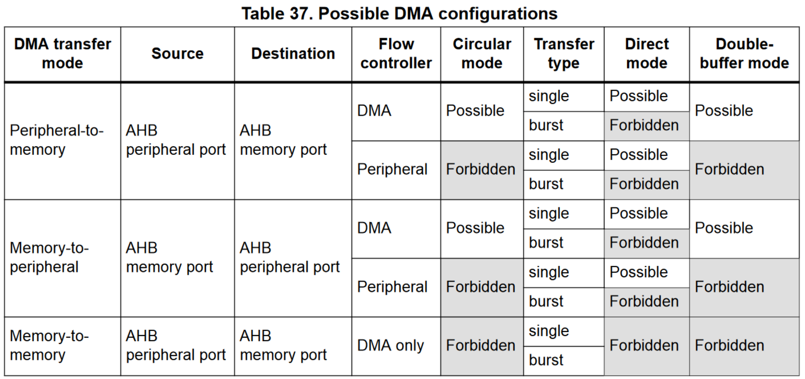
- If circular buffer mode is not enabled, you must manually reload the source address, destination address, and number of bytes to be transferred, into the DMA stream’s configuration registers prior to re-launching the stream. The DMA controller uses these registers for the address pointers and byte counter, with no separate mechanism to reload them in normal usage. This is pretty weak, as it wastes a bunch of clock cycles for short transfers.
- This chart:
Relevant Documents:
- DMA Training Powerpoint
- Using the STM32F2, STM32F4 and STM32F7 Series DMA controller
- Special thanks to Jared Raby for helping me understand this mess of a system.
Leave a Reply