 1999, First-Grade Homework")
Neon sign transformers are transformers used to power neon signs. Typically outputting 30mA at 4 to 15kV a neon sign transformer is a great toy to have if you enjoy arcs and sparks. But what is an NST exactly, how does it work?
An NST is a mid point grounded high voltage transformer. This means it has two high voltage outputs, each out of phase with the other. This means that a 10kV NST will have two 5kV outputs, and the potential difference across them will be 10kV. Mid point grounding makes insulation and manufacture easier since the maximum voltage relative to ground will be only 5kV in this case, and 5kV is a lot easier to insulate than 10kV.
Neon sign transformers have some iron between the primary and the secondary(s) and this gives the transformer high leakage inductance. Because of that they are current limited, usually to about 30mA. This means they do not need a ballast inductor and can be connected directly to the mains. Since these transformers are designed to run for years in near short circuit conditions NSTs can arc all day long without getting hot, and this makes them ideal for tasks such as a jacob’s ladder.
The current limiting brings me to another issue: NSTs have funky ratings. An NST might be labeled 10kV, 30mA, but it will never supply 10kV at 30mA. As you draw current from an NST the voltage sags quite a bit because that’s how the transformer is designed (it’s what a neon lamp requires). To figure out what current the transformer will supply at what voltage, check it’s volt-amp (VA) rating. If a 10kV NST is rated at 150VA and you’d like to know what current it can supply at 7kV simply do some division. 150VA / 7000V = 0.021A.
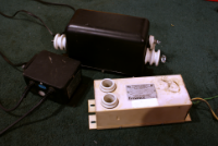 Neon sign transformers are one of those rare transformers that are designed to be electrician friendly, and thus user friendly. This means the mains input and high voltage outputs are easy to identify. Not only that but the case has some screw holes to mount the transformer. NSTs come in all sorts of shapes and sizes, three of which are shown to the left. In this picture I have a large terminal-type NST, a medium sized socket-type NST and a small NST from a labbatt blue sign. What type of NST you decide to buy is entirely up to your personal preference as they are all the same on the inside, a transformer encased in a brick of asphalt.
 Because underwriter’s laboratories had nothing better to do they published the UL2161 standard; a rule that requires all new NSTs to contain a secondary ground fault interrupter. This means that an sGFI circuit must be included in all new transformers –a circuit that will turn off the NST if a short circuit is detected. Since an arc is for the most part a short circuit this is bad news for experimenters. However, the UL2161 includes one exception for transformers with socket-type HV terminals. These transformers must bear the
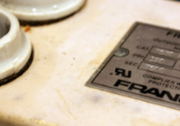
  or “recognized component” symbol. If you encounter a socket-type NST that bears the symbol yet lacks the UL symbol there’s a very good chance that it’s not sGFI protected.
Paralleling Transformers
Although they cannot be put in series neon sign transformers can be put in parallel for more current. That means longer, hotter arcs, and who doesn’t like that? Putting NSTs, or any other transformers for that matter in parallel is a relatively simple task.
First, make sure they are all rated at the same voltage! Do not parallel transformers with dissimilar voltage ratings or you will kill one or both of the transformers.
Second, make sure the transformers are phased correctly! Phasing is the direction of the transformer’s windings, and that dictates the “direction” of the AC wave. If two out-of-phase transformers are put in parallel the voltage cancels out and there is no output. It’s an easy task to determine the phasing of an NST.
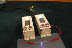 To determine phasing, connect a wire to one side of one of the secondary of one transformer. Then connect a wire to one side of the other transformers’ secondary. Bring the ends of these wires about 3 millimeters apart and secure them in place. Now put both primaries in parallel and plug the assembly into the mains. If you see no sparks the transformers are in phase and it’s safe to connect these wires together, and it’s safe to connect the other secondary side together as well. If you did see sparks such as the ones shown here the transformers are out of phase and you need to reverse the secondary connection of one transformer. This will phase the transformers up. ∎
Prom
You should definitely state that in pairing two neon sign transformers, there is at least half the voltage potential between them as in most cases there is a center-tap on the secondary winding which can introduce direct voltage potential between the two cases. If pairing neon sign transformers, they should be
Benjamin Miller
Hi Adam. I was wondering if you knew anything about Jacob’s ladders, the two long metal electrodes that are side by side on a transformer, but separate more further up which creates a self-starting arc traveling upwards. I need help with one I just made. It is an ignition transformer. I know you talked about microwave and neon sign transformers, which are also used to make a Jacob’s Ladder, but do you know anything about ignition transformers? They are meant to be arced more than any other transformer. I know that because they ignite gas or oil with a spark, but the Jacob’s ladder I got does not want to self-start. The transformer puts out 6000 volts on one secondary output and the ground is to the metal casing of the unit. The arc seems to get stuck at the starting spark gap where it should start up and climb the wires. When it reaches the top of the ladder, it should start up again at that gap, but it either does not start again, or gets stuck at that gap, which is really very annoying! I did almost anything to get it to work. The wires are all kinked out and smoothed, and are evenly spaced at the gap, but still, it won’t work. Do you need a wood base or platform to mount the wires or is it not necessary at all? I just bring the wires together in mid-air and try to even out the wires from the bottom to the top. Is it really tricky and time consuming to get the arc to travel just right? If you know any solutions or advice to this high voltage setup, email me when you get the chance. Thank you!