Hardware development is painfully slow. But it does consistently, albeit slowly carry on.
(or at least I try to convince myself it does)
Le’ Software: Motor Modeling
Well, in it’s simplest case, it is the following:
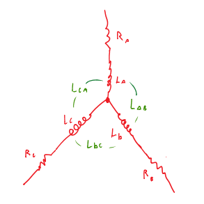
3 coils, configured in either a wye, or delta arrangement, each having an inductance, and a mutual inductance with the other coils in the network. Surrounding these coils is an arrangement of magnets; rare-earth, usually, which create a static field upon which the stator coils interact. In a plebeian sense, it’s the ‘job’ of the stator, to generate a rotating dipole vector that the rotor will do its best to ‘follow’.
Now, because the total flux in the system is constant, it’s possible to write a kirchoff voltage relation for the stator:
Where VR is the voltage drop due to ohmic losses in a coil, VL is the voltage dropped across a coil’s inductance, and Vgenerated is the motional back-emf generated by the rotor’s flux lines transversing the stator coil. For fun, we can break this up into the following matrix form assuming a 3 phase motor:
Where VR becomes a [resistance matrix] * [current vector], VL becomes an [inductance matrix] * the time derivative of the [current vector], and Vgenerated remains unchanged. Take special notice of the inductance matrix however, specifically note that “L AC” (et cetera), are the mutual inductances between stator coils. That is, the transformer-like inductance which will induce voltage in neighboring coils, when the voltage in the coil of interest is changing in time.
This can be broken up further:
And, assuming that all of our stator windings are reasonably equivalent, and that our windings are magnetically distributed 120 degrees apart from each-other, we may simplify to a somewhat-nicer looking equation:
~Where~
R = the average stator winding resistance
L = the average stator inductance
M = the average stator mutual inductance
I dot = the time derivative of current
Vmax = the maximum back-emf that will be generated
Theta_e = the electrical angle which describes the current back-emf, and also, the currents I(theta_e) and Idot(theta_e). For aesthetic reasons, I do not write I or V as functions of theta_e, but they indeed are!
The above equation also assumes that back-EMF is generated sinusoidally. That is, when you spin the motor and look at the voltage across a stator coil, you’ll see a sine wave. Due to reasons I won’t delve into here, this *is not true for every motor*.
With these substitutions made, it’s a bit more convenient now to smash everything back into as few matrices as possible:
 Admittedly though, this equation still doesn’t do us much good. It requires explicit values for every current in the circuit, and who even knows what the value of “M” is?
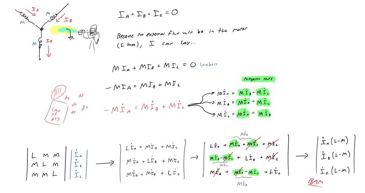
What if however, we assume our currents to be balanced? That is, there is some relation Ia + Ib + Ic = a constant, which in theory, would let us simplify our matrices a bit.
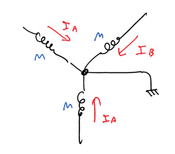
Could this be the case? Well… certainly not if the motor is grounded! Just refer to the left figure, and you’ll soon see why.
( For those bad at where’s waldo: If a ground exists, Ia and Ib and Ic can all leak out through it, independent of each other! )
A simple solution to this problem is to *not* ground our motor. In doing so, we end up with the relation Ia + Ib + Ic = 0, which lets us make the following simplifications:
Which then becomes the rather trivial relation:
Look at that, our inductance matrix is now isomorphic to an inductance scalar. Hot damn!
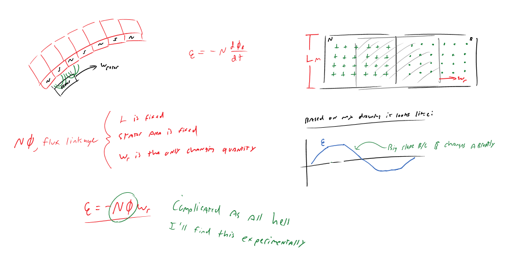
There are still some more unknowns to kill, however. Specifically, what exactly is Vmax?
Well, Vmax, by our prior definition, is the maximum electromotive force generated by the rotor’s magnets flying past the stator’s coils. As such, per one of maxwell’s relations it’s a linear function of the rate of change of magnetic flux in the stator coil.
With this argument in mind and the constraint that no magnetic components are changing in physical size, Vmax must then only be a function of flux linkage and angular velocity of the motor!
And with that…
Look at that: a model which contains quantities that are either all constants, or physical elements we can directly measure. Nice!
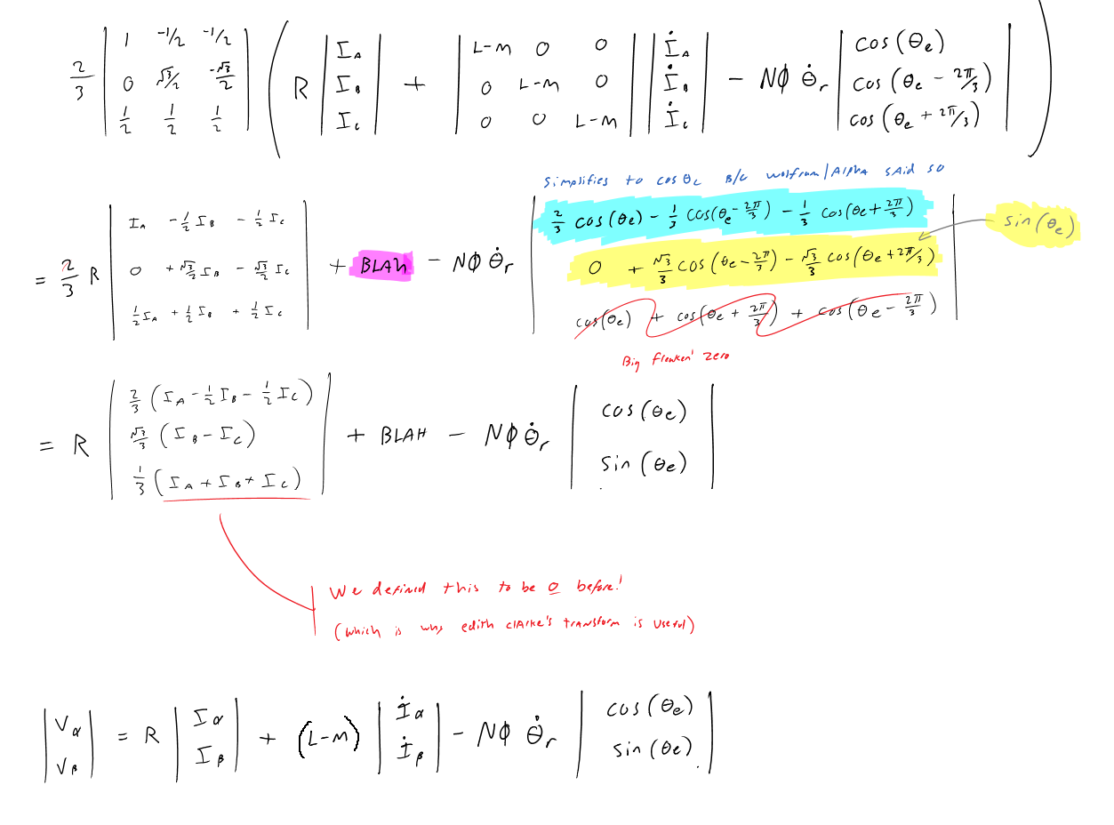
But, this matrix representation is still not all that useful to us. I say this because it’s impossible to fully represent the model in this form, with conventional engineer’s tools like phasors. So, we need some sort of transform to take us from this balanced, 3-phase representation into something of the form e^ix, or restated, from a 3-tuple representation into a 2-tuple representation.
Thankfully, a lady by the name of Edith Clarke figured out how to do this in the 1960’s.
Yay, we just gave one component in our current/voltage tuples the boot!
Edith’s transform can be thought of as a geometric transformation: three vectors, rotating synchronously in space, are projected onto the complex plane. Assuming these vectors are “at theta=zero”, that is, oriented in such a way that vector A is co-linear with the real (alpha) axis, then we are left with a situation in where the two other vectors are pointing the other direction, and are offset 60 degrees from the real axis, or correspondingly, 30 degrees from the imaginary (beta) axis.
Now what is the real part of a 30-60-90 triangle on the complex plane? sin(60) = sqrt(3)/2.
What is the imaginary part? cos(60) = 1/2.
That in mind, take a look at the transformation matrix, and it all should make a lot more sense :-).
Now, we still have that ugly back-emf vector, |cos(x), sin(x)|. What can we do about that?
Well, in vector space, a 2-tuple is for all intents and purposes isomorphic to a complex number, which is also a 2-tuple. (read: “ordered pair”). So, with the convenient relation:
e^ix = cos(x) + i sin(x)
We can say that:
|cos(x), sin(x)| for our purposes, is equal to e^ix
Ain’t that somethin?
In hat notation, our equation is now beautifully simple!
Where V_hat, or any other similar vectors are equivalent to ( V_max e^i theta ).
One might ask though, how is this two-dimensional equation useful in our 3-phase motor? What good does it really do us?
To answer that question, it does us good, because instead of three phase shifted cosines, we now only need to keep track of one sine, and one cosine component. This is a much easier proposition for DSPs to handle, and, because we used a linear transformation to get this equation, it’s possible to use an equally trivial transformation to bring us out of the complex plane, and back into three-phase space. Specifically like so:
I_phase_a = 3/2 Re[I_hat]
I_phase_b = 3/2 ( -1/2 * Re[I_hat] + √3/2 * Im[I_hat] )
I_phase_c = 3/2 ( -1/2 * Re[I_hat] – √3/2 * Im[I_hat] )
Where I_phase_n is a current, itself linearly related to the PWM value you’d feed to some leg of a mosfet bridge.
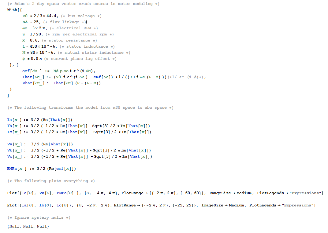
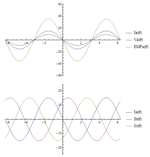
But that’s enough of this, let’s toss everything into mathematica to prove I’m not giving you crap!
Bam, would you look at that. Those curves sure look like a brushless motor to me.
With the proper constants chosen they should represent any motor, even a Segue motor!
Le’ Hardware: Another $100 worth of power electronics
It is often the case that something you discover during a project, completely invalidates all prior work on the project. Sometimes this may happen more than once.
After modeling my motors we soon needed to fill in the constants, flux linkage in particular. How does one go about finding that?
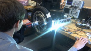 Well, you use lots of scotch tape, a power drill, aluminum foil, two LEDs and an oscilloscope.
SCIENCE.
Too much of it to handle.
Anyway… in this case, the maths above soon revealed that my 44V of lithium power was not going to be enough for Segue. That is, the back-emf generated by my motor will equal 44V, when Segue reaches a linear speed of 21 km/h. …which is *not* 40 km/h!
So ladies, gentlemen and children of the internet, I present Segue v5.
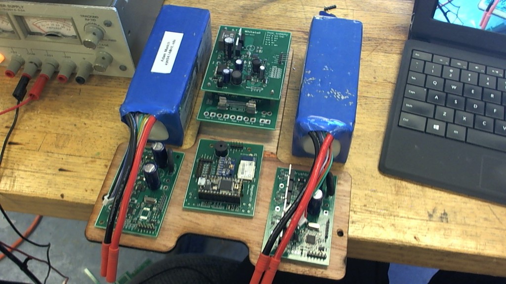
After getting fed-up with de-, then re-soldering hundreds of components every time a board was revised, I decided it was in my best interest to go back to the “multi-pcb-with-ribbon-everywhere” solution. That is, Segue will have 5 independent boards:
Cellsniffer – A 24 cell (88V) lithium-ion pack monitor and balancer.
S.T.S. Whitetail – A board full of buck converters, and an 88V 4A boost converter.
2x Brushbuster – A new motor controller board, equipped with super-badass 8mohm 150V mosfets and a C2000 DSP
Seguebrain – A board with a bluetooth radio, an IMU and a cortex-M4, among other things.
Now, as much as I would love to say I’ve gotten things working; IE, having a nice stochastically-spun motor available to show you, I don’t.
Why?
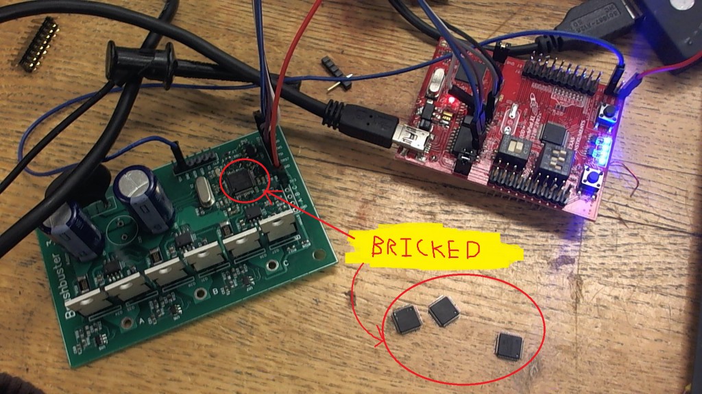
Because, programming a C2000 piccolo is evidently quite a pain in the ass. That is, code composer studio for some reason likes to hang during flash erases, which just so happens to brick my DSP.
I’ve yet to figure out why this is happening, but to be honest, I’m a bit fed-up with these ICs already. I mean really, *WHO STORES LOCKOUT PASSWORDS IN PROGRAM FLASH*. Is is really that much more expensive to have a 64 byte bank of EEPROM memory, explicitly for storing such configuration data?
Assuming all other TMS320 products do the same, remind me to *never* use a TI DSP inside an aircraft, or some other similar mission-critical system. I say so, because it would be really, really bad if you locked-up such an IC, buried deep inside an apollo-computer construction actuator control box and/or something of equal “this is going to be really hard to repair” stature.






Leave a Reply