Plasma Speaker II
I've seen multiple designs for a plasma speaker online, and quite frankly most of them are not very good. Some problems I noticed were constantly blowing up MOSFETs, distorted audio, excessive heating of the MOSFET(s) etc.I was shown a nice circuit on 4HV that uses a half bride and pulse width modulation. I modified the circuit to my liking and it worked very well.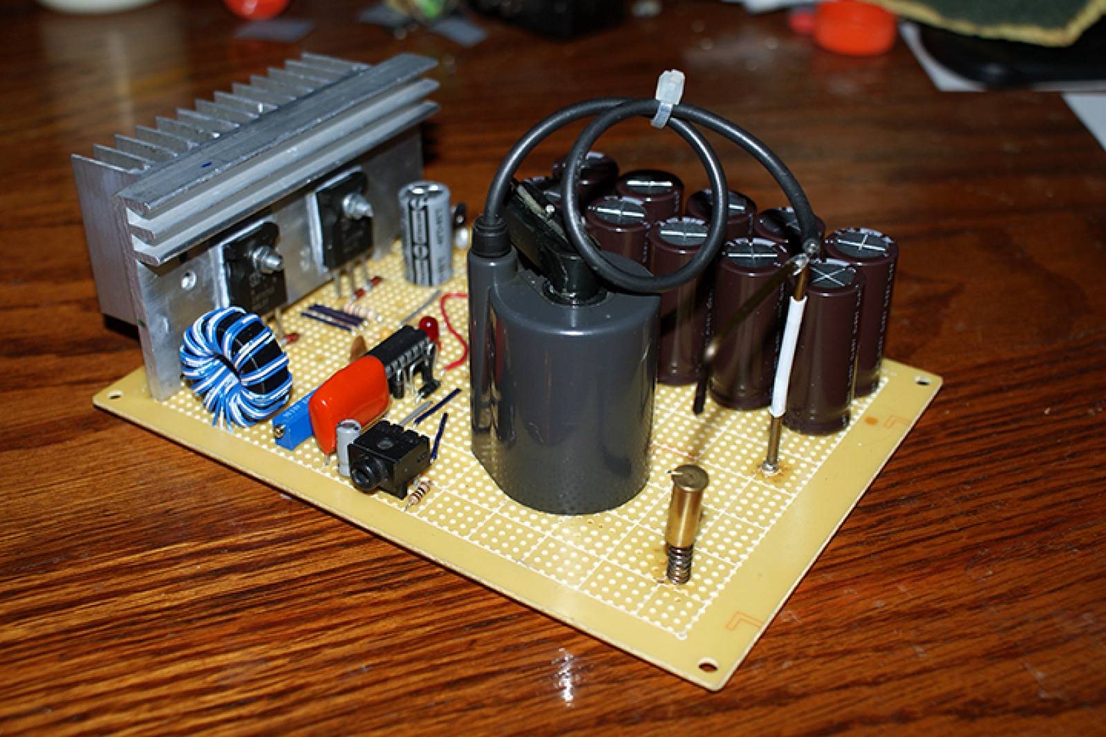
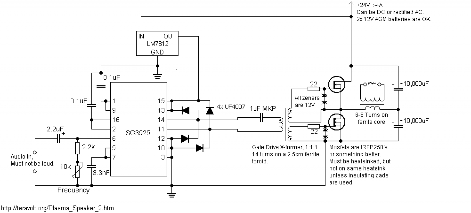 Some important notes about this circuit:- The 10k pot still controls the frequency, and a lower frequency means higher voltage. The sweet spot was around 50kHz for my flyback, but it may be different for yours. It's a trivial matter to turn a knob though.- The 1uF cap must be either an MKP, mylar or foil cap. No electrolytics! Its function is to block excess DC current from flowing through the transformer, since capacitors block DC yet pass AC. - There is a gate drive transformer. What this does is provide an isolated gate drive for the upper mosfet preventing it from dying, and it is required for the circuit to work properly. A GDT is simple to make: all you do is take a bundle of 3 wires and wrap them around a ferrite toroid. I used 14 turns on a 2.5 centimeter toroid, but other designs may work better for you. Ferrite toroids can be bought for about a dollar online if you don't have one laying around.- Too loud a signal can and will overload the chip. When you put audio in, set the volume to 0 then slowly turn it up. When the music becomes distorted that's as loud as it's getting. It's not terribly loud, but it is still easily heard in a quiet room. You must have a clean audio source too, no electrical noise. I used my computer, and it would appear that iPods don't work too well. It's trial and error with the sources.
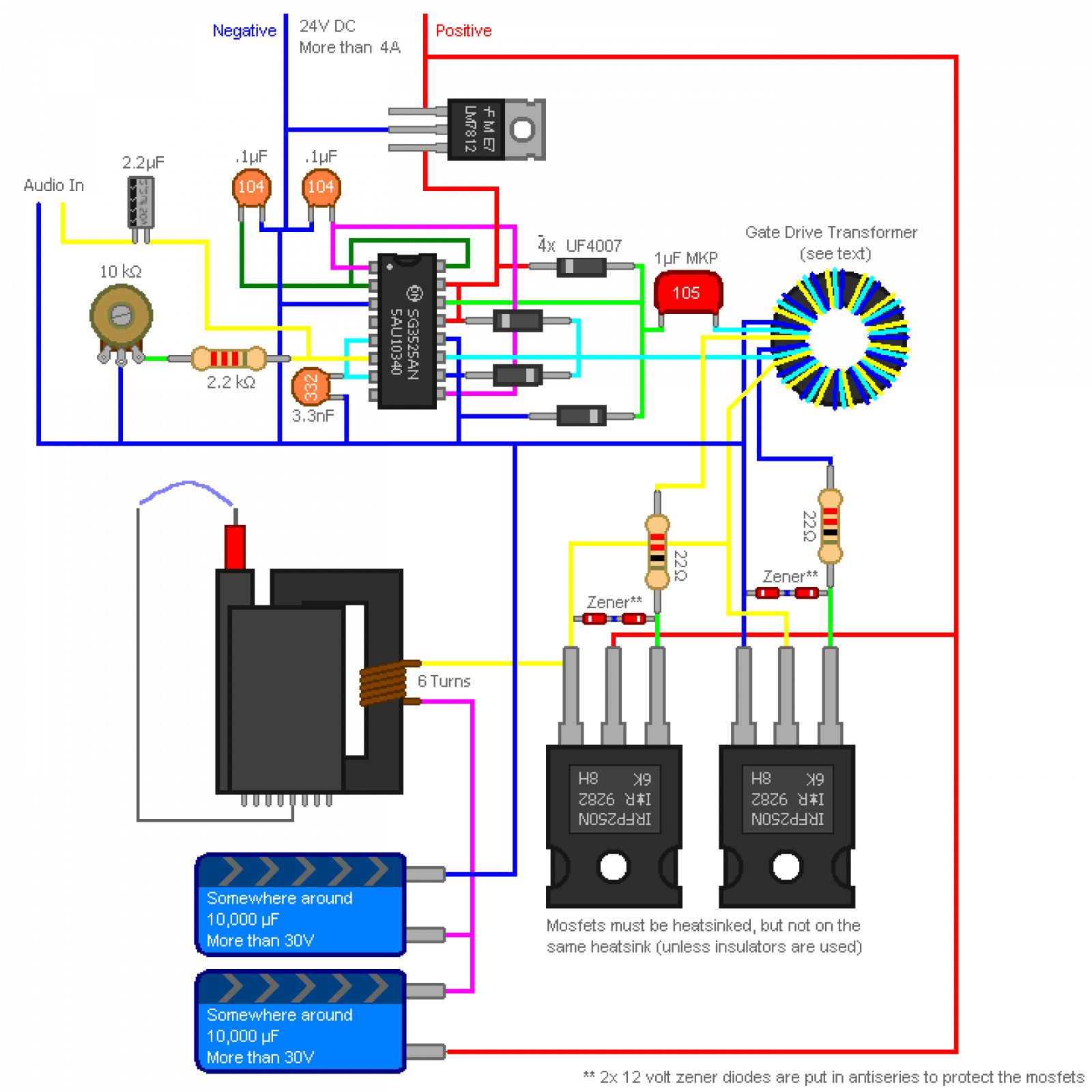
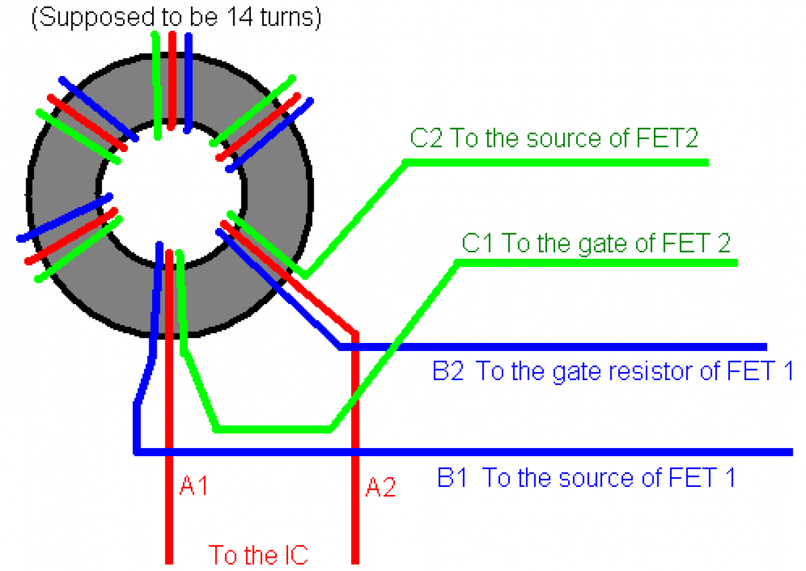 The GDT must be phased correctly, but what is phasing you ask? Phasing is the direction of the coils in a transformer. You must make sure that one output winding is reversed; this reverses the signal that it puts out. The mosfets in this half bridge circuit are supposed to "flip flop" --one turns on as the other turns off. The gate signals of the fets are supposed to be opposite for this to happen. If both the signals are the same, both the mosfets will turn on at the same time and they short circuit or possibly explode.So essentially, one of the coils on the transformer must be 'reversed'. A properly phased transformer looks like this on a scope; one wave is inverted.
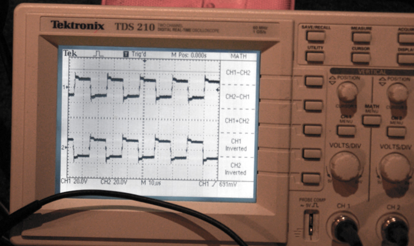
Gather the Parts
You'll need some parts for this speaker, not too many but some.- 4x UF4007 diodes - 4x 12 volt zener diodes- 1x SG3525 IC- 1x LM7815- 2x 22 ohm resistors- 1x 2.2k resistor- 1x 10k pot - 2x 0.1uF (104) capacitors- 1x 3.3nF (332) capacitor- 1x 1uF (105) MKP capacitor- 1x 2.2uF electrolytic capacitor- 2x 10,000uF electrolytic capacitors If you use 40v 8000uF caps instead you can apply 36V and make the arc even bigger and louder. Just make sure to replace the 7815 with a 7818.- 2x IRFP250 mosfets. You can also use some better fets, the lower the RdsOn the better. Just make sure they can handle at least 200V as flybacks make some nasty back EMF.All of the above parts can be bought at [url=digikey]digikey[/url], or if you live in europe, [url=Farnell]Farnell[/url]Other components:- A #flyback-transformer. You can get these out of old computer monitors, TVs etc.- A ferrite toroid. These may be inside computer monitors, but if you can't find one get it here.- Some 18awg wire.- Some 24awg wire, the wire from inside of a telephone cable works great.- 2 heat sinks, you can get them from a computer monitor. You'll need to use your scavenging abilities here. If you use 1 heat sink make sure you use some insulating pads.- Thermal goopThe Circuit
This circuit is considerably more complex than my other speaker, but it still uses the same principal:By sending more current through an arc, you produce a hotter arc. Hotter arcs will have a higher pressure, and by varying the current through an arc you create varying pressures, something commonly known as sound. Now this circuit uses PWM to accomplish that. By shortening the width of the pulses to the mosfet's gates you can reduce the current that flows through the flyback. By changing those pulses to the tune of music, the arc's current and pressure will vary in tune with the music, thus producing music!Gate Drive Transformer
There is a gate drive transformer in this circuit. What this does is provide an isolated gate drive for the upper mosfet preventing it from dying, and it is required for the circuit to work properly. A GDT is simple to make: all you do is take a bundle of 3 wires and wrap them around a ferrite toroid. I used 14 turns on a 2.5 centimeter toroid, but other designs may work better for you. Ferrite toroids can be bought for about a dollar online if you don't have one laying around.