ZVS Driver
A "ZVS driver" is a self resonant oscillator; a very simple circuit that can oscillate a large amount of power with little loss. It is normally used for making the sine wave needed for driving high frequency transformers such as those found in LCD cold-cathode lamp drivers and other applications.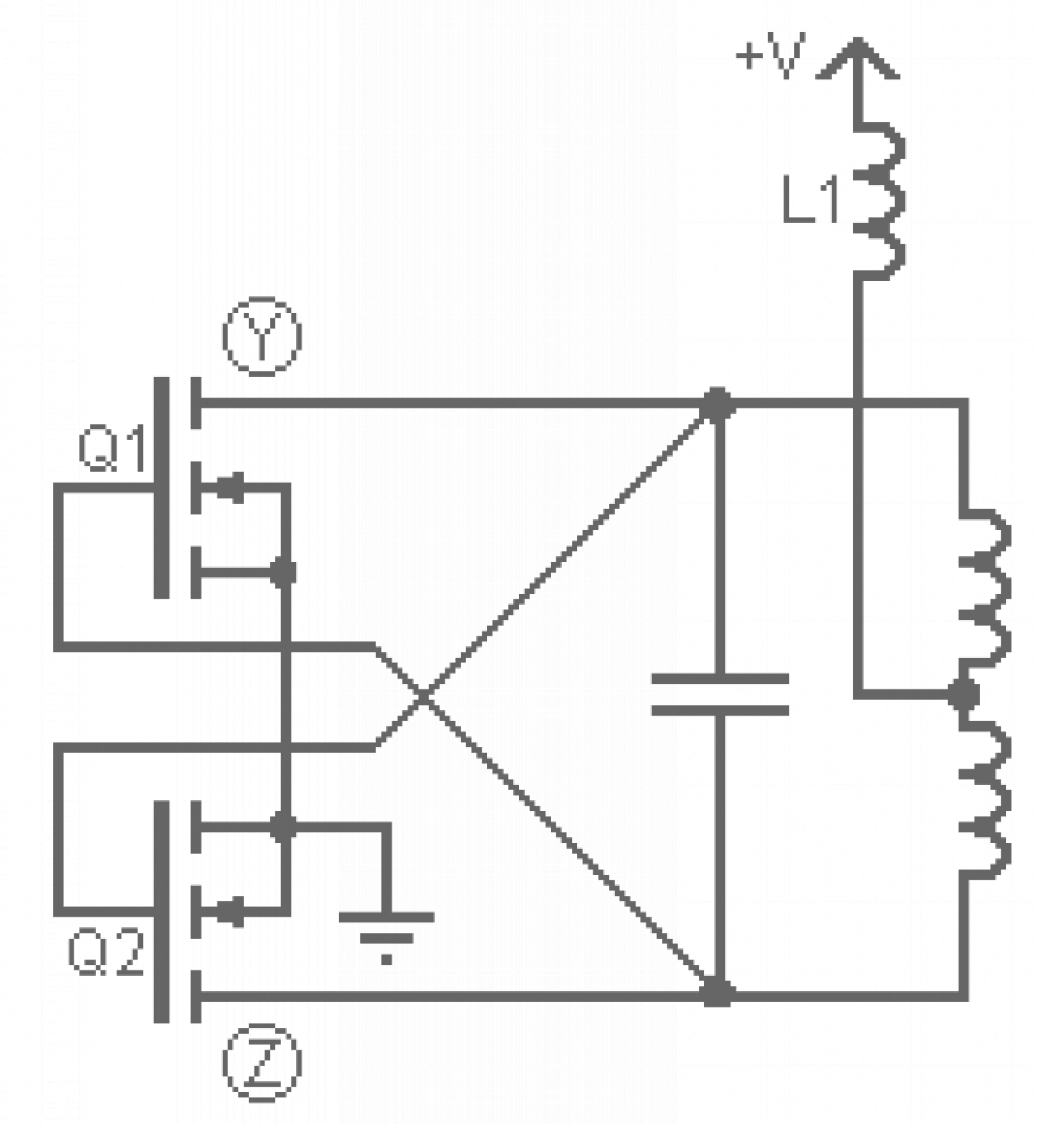 - When power is applied at +V current starts to flow through both sides of the primary and on to the mosfets' drains. - Simultaneously that voltage appears on both of the mosfets' gates and starts to turn them on. Because no two components are exactly alike one mosfet turns on a little faster than the other one and more current can then flow through that fet. - The extra current flowing in that side of the primary robs the gate current from the other fet, and a capacitor forms an LC tank with the primary and the voltage proceeds to rise and fall sinusoidally. If it were not for that capacitor the current would continue to increase until the transformer's core saturated and the mosfets exploded.Imagine that Q1 was the first to turn on. The voltage at point Y will be at near ground while the voltage at Z rises to a peak and falls back down as the LC tank goes through one half cycle. As the voltage at Z passes through zero the gate current to Q1 is removed and the mosfet turns off. The voltage at point Y is now allowed to start rising and Q2 turns on. That mosfet clamps the voltage at Z to ground; something that makes sure Q1 stays off. This same process repeats for Q2 completing the other half cycle, and the oscillator continues cycling. In order to prevent the oscillator from drawing huge peak currents and exploding, L1 is added in series with +V as a choke. The LC impedance is what limits the actual current (the choke just mitigates current spikes).A keen eye will notice that this oscillator is zero-voltage switching (ZVS), meaning that the mosfets switch when they have zero volts across them. This is good because it allows the mosfets to switch when they are carrying the least power; something that for the most part eliminates the switching losses which generate huge amounts of heat. This means only small heat sinks are needed, even when oscillating 1000 watts!Being a resonant oscillator the frequency that the royer will run at is determined by the inductance of the transformer's primary coil and the capacitor. You can use the following formula to figure this out:f = 1 / ( 2π * √[L * C] )f is the frequency in HertzL is the inductance of the primary in HenriesC is the capacitance of the capacitor in Farads
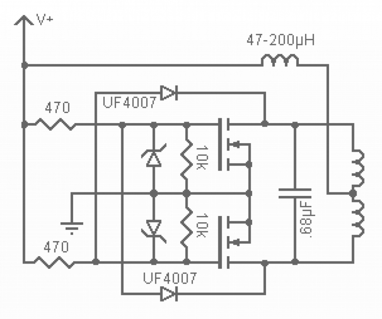 - The 470 ohm resistors limit the current that charges the gates as too much gate current can cause damage. - The 10K resistors pull the gates down to ground to prevent latchup; a process in which the mosfet gets stuck on.- The Zener diodes prevent the gate voltage from exceeding either 12, 15 or 18V depending on the zeners you use.- The UF4007 diodes pull the gates down to ground when the voltage on the opposite leg of the tank is at ground.One may notice that instead of charging the gates with the LC tank we are instead using +V to charge them up and we are using the LC tank to discharge them via the ultra fast diodes. This improves the overall performance of the circuit.Here is a pictorial schematic for those who desire one :-)
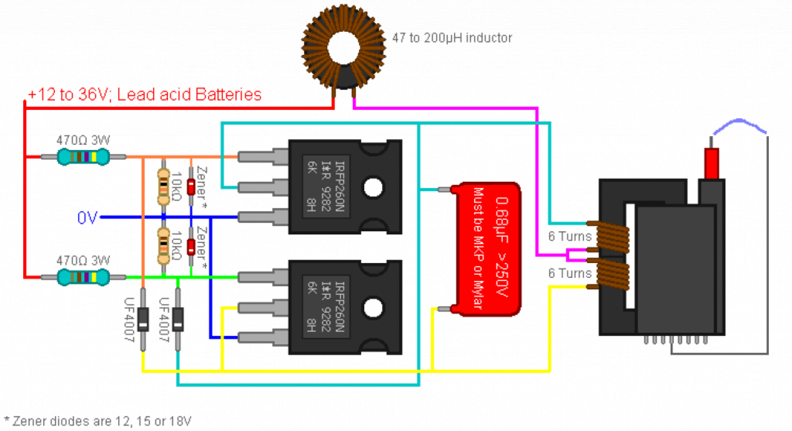
How it works
An actual circuit
Now in reality mosfets are rather fragile components and if the gates are +/- more than 30V from the source the mosfets will be destroyed, or at least degraded significantly. In order to prevent this scenario from occurring we'll need gate protection; something easily added with a few extra components.