The Fryback Transformer
Ladies and gentlemen of teh internetz, I present to you a marvelous device that will revitalize your health and bring wondrous wealth and prosperity to your families and all future generations. Straight from Nikolai Tesla's labs I bring you a fantastic revelation in high voltage transformer technology, made with nothing but the latest and greatest materials this magnificent transformer will supply all the milliamperes you'll ever need along with more than nine thousand volts! Such mind boggling wonders can be experienced with this remarkable transformer...Because I had nothing to do and had an empty piece of ferrite I decided to make the largest AC flyback transformer that I could. Now if you don't care how I made it you can just watch the video and subscribe to me, but if you do you may read the text below and learn how to make your own.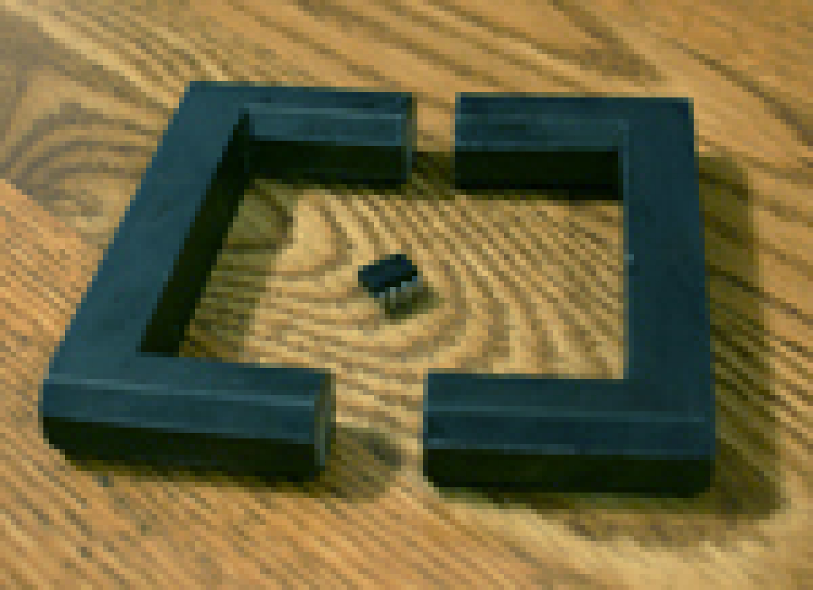
 When powered by a #ZVS and run at 36V the thing makes some 5 inch long, 2.5cm fat arcs. The voltage is about 20kV while the current must be 100mA or more. That's all well and good, but when fed 48V the fryback really shows what it's capable of. It outputs 15kVrms (21kVpk) and the current is... a lot. The arcs I can draw from it are 1 foot long! My fryback likely can't handle more than 48V because the core gets very hot and is probably in saturation. The secondary could theoretically handle much more power though, as it stays nice and cool, and the inter-winding voltage is only 1250V while I used 4kV worth of insulation.
The core
First you'll need to find a suitable ferrite core. The one I had to use was made at least 50 years ago and was part of an old flyback who's winding pretty much fell apart. Because I'm a klutz the core has a crack in it, though when repaired with superglue it's good as new. What's special about this core is it has a huge winding window, and that allows for quite a large secondary. Cores such as this can be found online if you look hard enough, one this size might cost you $14.The secondary winding
I had a bunch of 28AWG magnet wire and nothing to do with it, so I decided to use this wire to make the transformer's secondary. It' a little thicker than I'd like, but the thinner stuff I had was 40AWG which was way too thin. I chose to make a disk shaped secondary for a number of reasons;- Inter-winding capacitance is reduced and the transformer can run at higher frequencies.- Because there are few windings per layer, there will not be a large voltage difference between layers.- Not very fat, so I can use tape to make it.- Disk shaped secondaries look cool.Ideally one should use kapton tape to make a transformer, but I had to make do with what I could get at the hardware store. Therefore I bought some red electrical tape and some teflon pipe thread tape; --the nice 3M tape that comes in the little plastic containers because it is very stretchy and very sticky, not the POS dollar store stuff. After some testing I found that the electrical tape failed at 800V while the teflon tape failed at 1kV. Because of this I'd need a couple layers of tape to prevent failure.The Secondary: Coilform
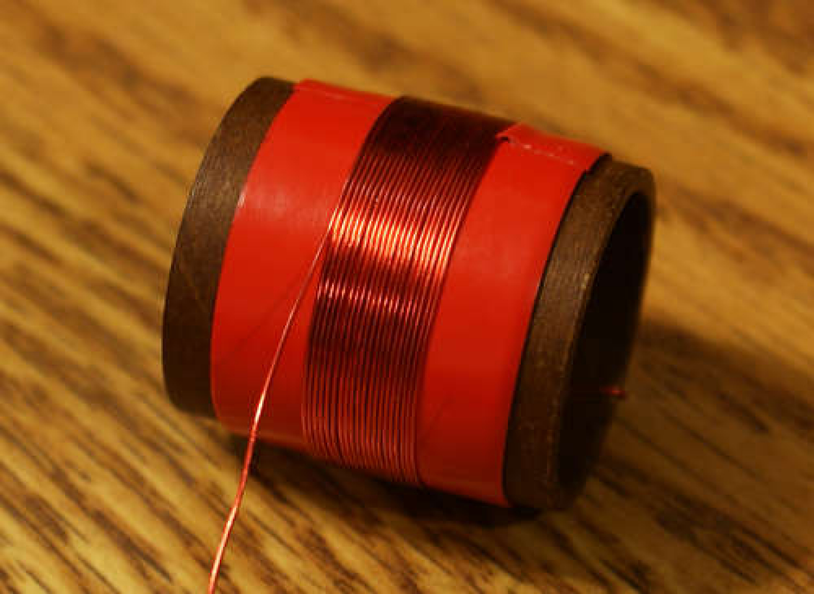
The first step is to find a nice cardboard tube and wrap some electrical tape on it, then wind some wire around that. In order to prevent failure the wire must not come close to the edges of the tape. I managed to fit about 23 windings nicely in the middle.Tips:* Don't take the magnet wire all the way to the ends of the tube.* Don't make the entire winding layer more than a half inch wide. If you do there will be insulation issues.* Wrap tightly and make no crossed turns.* Use superglue to hold the wires in place.The Secondary: Insulation
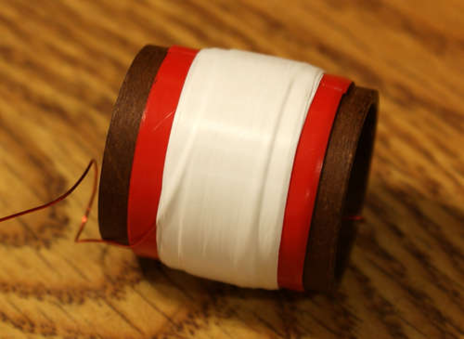
The next step is to provide some insulation for the layer by wrapping 5 layers of teflon tape around it nice and tight --something critical to prevent it from going up in flames. 5 layers should be good for 4kV, but I personally wouldn't trust it with more than 2.To calculate your inter-layer voltage, take the output voltage you're aiming for and divide that by the number of layers, then multiply that by 2.Say I want 30kV and I have 40 layers. (30,000/40) * 2 = 1.5kV inter-layer voltage, not too bad considering I used 4kV worth of teflon. Since teflon is very deformable it conforms to the windings and squeezes out air that could cause corona which eats away at the insulation.The Secondary: More layers
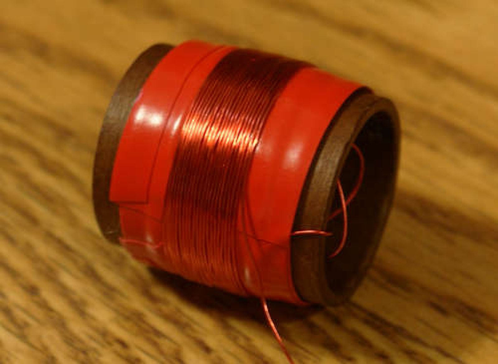
Now put on one layer of electrical tape, then start winding again.Secure the wire with super glue, then cut strips of electrical tape and place beside the coil. In the picture there is only one strip (on the left), but two are required to support the next layer.The Secondary: Even more layers...
Now repeat that until your brain melts!I decided to put 40 layers in my fryback, a task that took me 25 hours! Albeit I was watching TV at the same time, but it's still a daunting task. Take care to not break the wire coming out of the center!The Secondary: Output leads
Since magnet wire is fragile one must attach some silicone insulated wire to the windings and super glue it in place. Silicone wire is a good choice because it is very flexible and it can stand up to HV quite well. Not only that but super glue sticks to it very well. Unfortunately it costs a little more than regular plastic insulated wire.The Secondary: Coating
The newly made secondary coil must be covered in liquid electrical tape; about 4 coats.The liquid tape preforms 4 functions:* Prevents water from getting in.* Prevents the electrical tape from sliding off of the cardboard tube.* Adds some insulation.* Makes the thing look that much better.The Primary
Every transformer needs two windings to work, so the primary winding was made by taking two strands of 18AWG wire and wrapping a 4+4 turn center tapped primary around a paper and tape form. Notches were cut in the coilform to prevent rotation.Assemble it
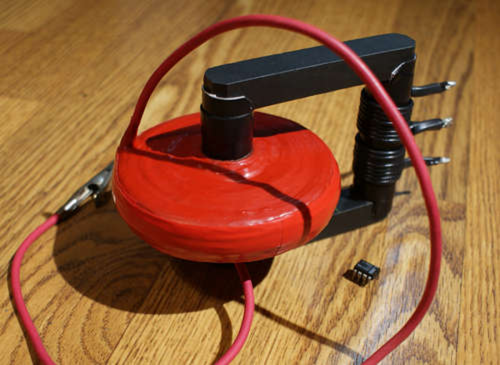
After adding some tape to the core pieces to make an air gap I slid the core in the paper tubes and the friction held it in place. When powered up the core will clamp together because of the magnetic field, so no external clamp is needed. And here we have the largest disk AC flyback yet made, a transformer which I have aptly named "the fryback".