Flyback Transformers
Also referred to a Line Output Transformer, the flyback transformer is a high frequency, high voltage transformer most often used to power cathode ray tubes. Flybacks are capable of generating some decently high voltages, typically anywhere from 10 to 35kV.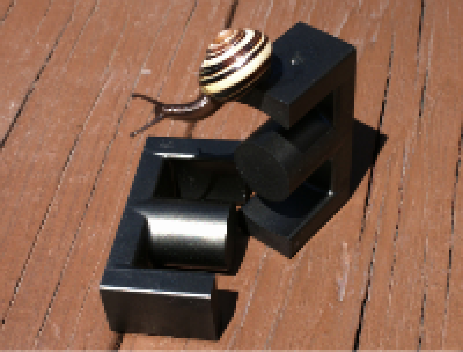 A flyback core consists of two separable "U" cores held together with a metal clamp and a little bit of glue. If you happen to break the ferrite core don't fret, using a small amount of super glue it can be reassembled like new. It bonds ferrite very well, so you'll only have one shot to line things up right!Closer inspection of the flyback's core reveals an air gap. This gap increases the leakage inductance of the transformer, decreases the permeability of the core and increases the transformer's ability to handle current.
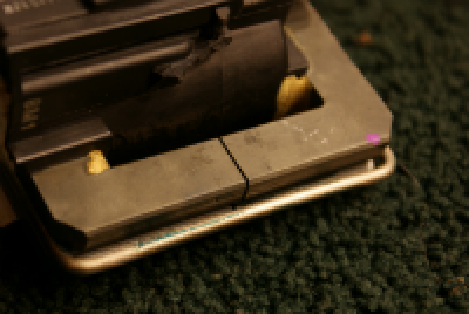
 DC flyback transformers can take quite a bit of abuse before failing. Typically they are able to output up to 30kV without ill effect, though some of them can handle voltages on the order of 50kV. Almost every DC flyback will fail at voltages greater than 70kV; the insulation just can’t withstand that.
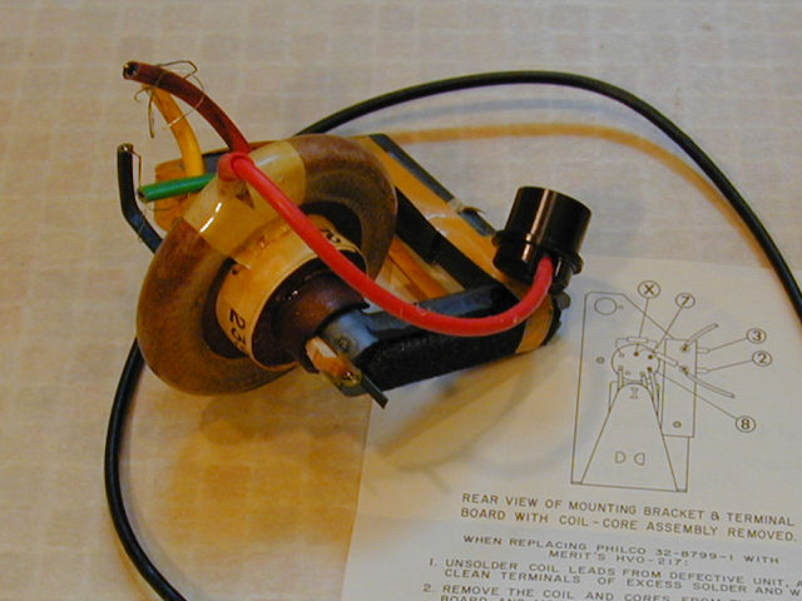 The second type of AC flyback (found in circa 1968 televisions) consists of turns of wire insulated from each other with layers of tape. The entire transformer is then covered in asphalt for insulation. These types of flybacks are very prone to failure when outputting more than 15kV and caution should be used when playing with them. The tar will usually be cracked, yet it is possible to re-sculpt it as I have done here using a soldering iron and a couple hours time.
 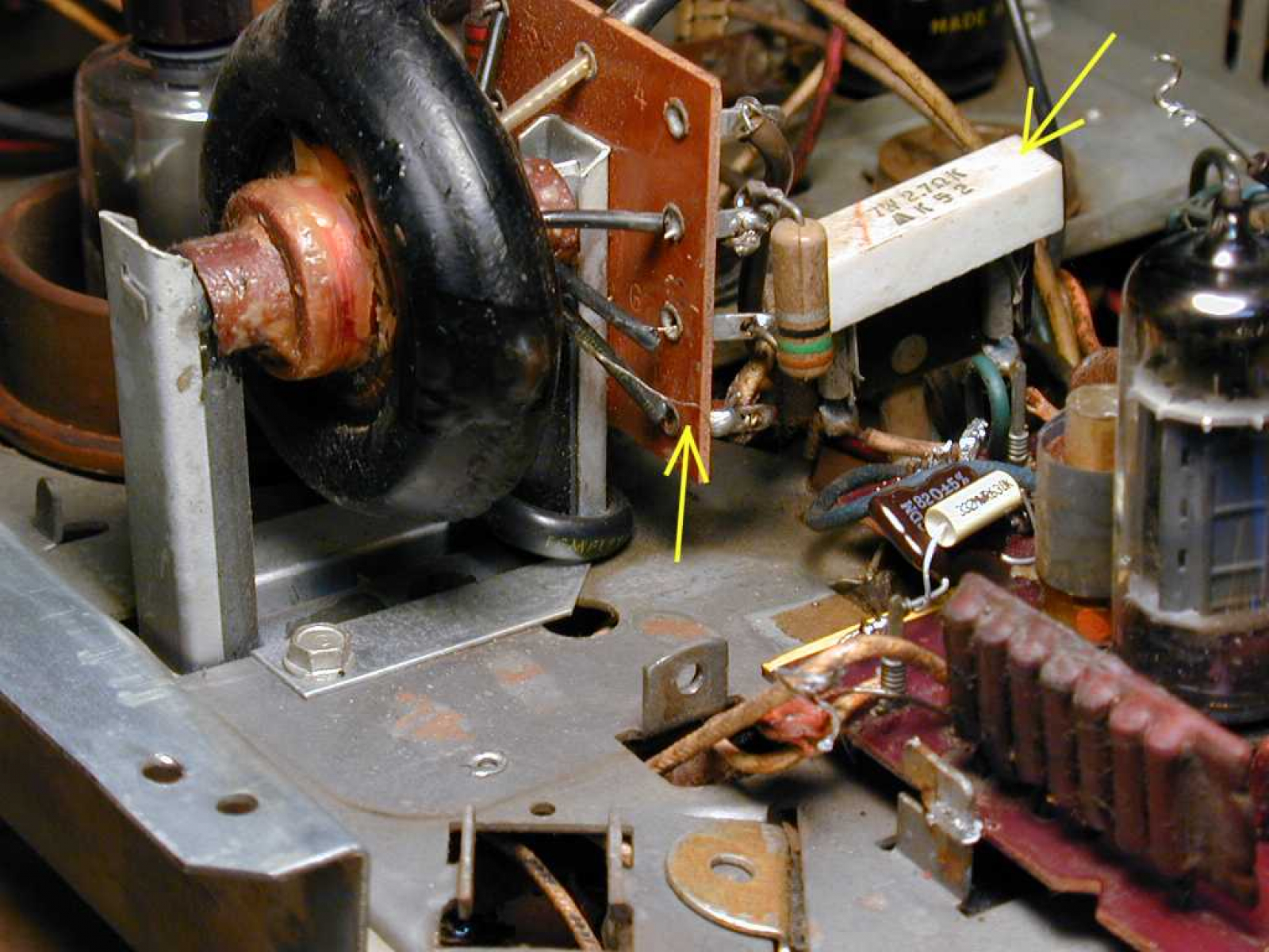 The last type of AC flyback is an epoxy potted FBT much like a DC one, and these are very nice transformers. Sometimes they will have low voltage windings insulated with paper, windings I call the “evil core” due to its high failure and combustion rate. However because the high voltage winding is a separate entity from the paper windings this evil core can be removed and replaced with a quantity of paper; something that will make the transformer all that more reliable.
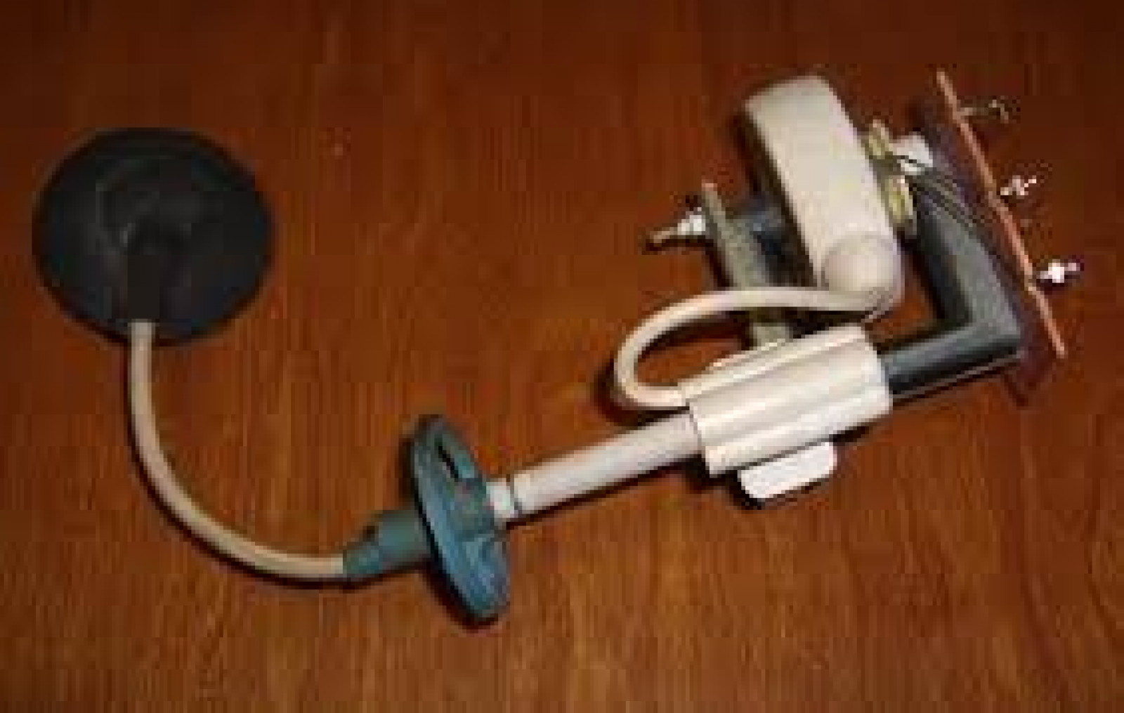
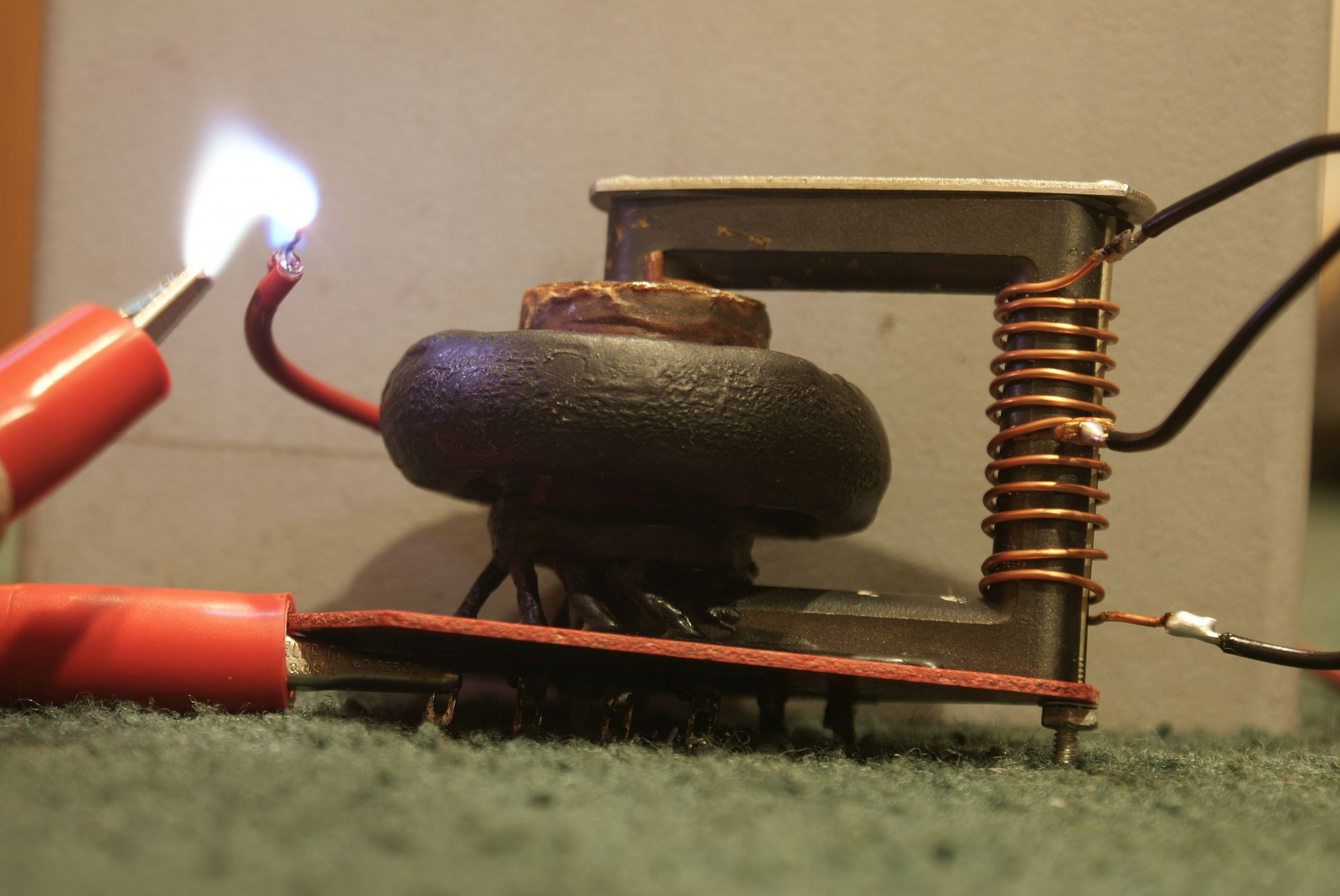 Flybacks require a high frequency input: they will NOT work on 60hz. What frequency usually varies since each transformer has its own resonant frequency, but anywhere from 15 to 50khz is usually best. Higher frequencies give higher currents but lower voltages.There are many ways to generate the high frequency AC needed for a flyback, including but not limited to a zvs oscillator and a mosfet half bridge. How you choose to power your flyback is a matter of personal preference. Typically for more voltage a half bridge driver would be ideal and for more current a royer would be the driver of choice.Because the pin outs for a flyback transformer are usually very hard to find, by far the easiest method of finding the high voltage ground would be to bring the high voltage output to the pins at the bottom of the transformer and find the one that supplies the strongest arc.That’s all there really is to say about the flyback transformer! ∎
Ferrite Cores
Flybacks are not like most other high voltage transformers because they do not have an iron core. Instead their core is made of ferrite; a material that is a rather poor conductor, has a high magnetic permeability and and suffers from low hysteresis losses --three attributes which make it well suited for high frequency transformers. Because there are more cycles per second a high frequency transformer is able to push more power through a smaller core. What does this mean to you? It means that instead of requiring a 25lb iron transformer to get 15kV at 10mA you only need a 1/6lb flyback. Size isn't the only advantage when it comes to HF transformers though; efficiency is also improved because there is less material to magnetize.DC flybacks
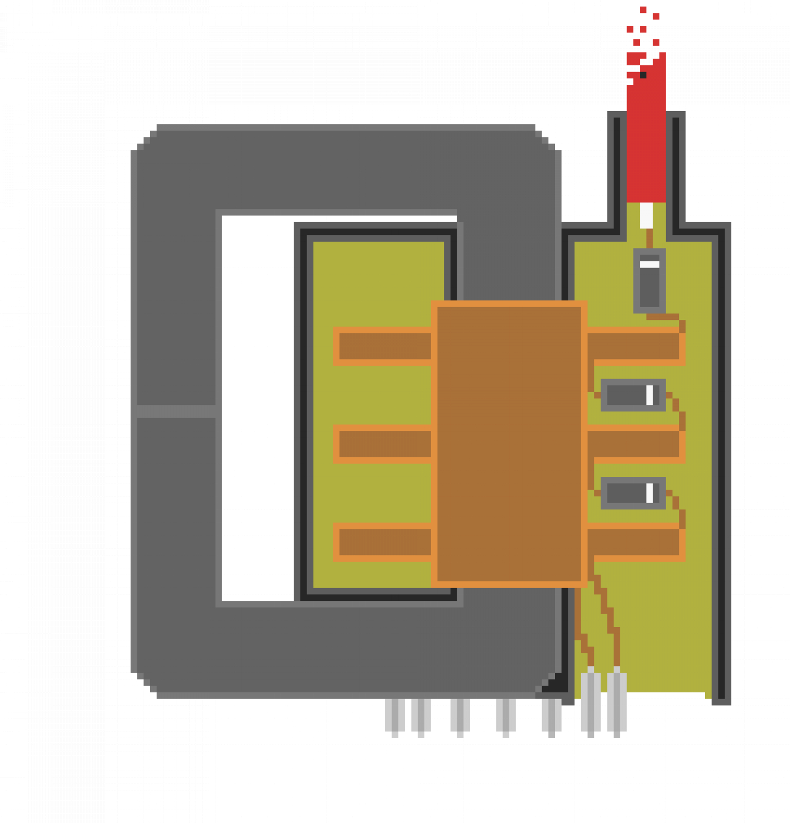
The most common type of flyback is the DC flyback transformer. Undoubtedly the most reliable flybacks due to their plastic insulation, the DC flyback contains an internal diode that half wave rectifies its positive high voltage output. The DC flyback comes in all sorts of shapes and sizes, yet it is most often just a black lumpy looking thing with a red high voltage wire sticking out.Their construction is as follows: Inside a DC flyback there are three or more “pancakes” series connected using some rather beefy high voltage diodes. One side of this primary pancake stack is connected to a pin at the bottom of the transformer, while the other side will be connected to a red high voltage wire sticking out of the top. In the center of these pancakes (also connected to the pins) will be an assortment of low voltage windings that are all but useless to the hobbyist yet very useful to the television manufacturer. The entire assembly is then vacuum potted with epoxy, never to be seen again.AC flybacks
Before the days of the silicon diode the only high voltage rectifiers available were big thermionic tubes. Now embedding a vacuum diode in a transformer isn’t exactly practical, so the diode was kept external from the transformer. Luckily for us that means the flyback outputted AC rather than DC. Unlucky for us, there aren’t that many left…Also rather unlucky for us, most AC flybacks tend to have mediocre insulation between their windings, and because of that they are more prone to failure than the DC ones. Generally there are three ways these flybacks were constructed:Pre 1955 flyback transformers were nothing more than a pancake of wire wrapped around some more wire with the windings held in place by witchcraft. These flybacks are because they are easily submerged in oil, and when in oil they can output up to 30kV without failure. In air I wouldn’t let it output more than 10kV. They are usually covered with shellac insulation, but it will probably be cracked something fierce. Personally I would chip it off and dip the flyback in paraffin wax to supply it with better insulation.Powering a flyback
Flyback transformers have an internal primary winding and this is how they are powered in a television. Unfortunately this primary is made of some rather thin wire and has lots of turns; this means you need something like 170 volts to get any decent output out of the flyback. More turns means the transformer has a lower windings ratio, and that means to get the same amount of voltage out you’ll need to feed more voltage into a 1:20 transformer than a 1:200 one.Thankfully the ferrite cores on flyback transformers are exposed, so it’s trivial to wind your own primary coil on the core. Because the new primary is on the opposite side of the core from the secondary there will be some current limiting, but it’s not too noticeable. Many different primary configurations are possible with a flyback, just by wrapping some wire you are able to choose between a regular primary, a center tapped one, a tickler primary –anything your heart desires. The primary on the flyback shown here is a center tapped one.